Modern IT Training Lab Setup: 2026 Blueprint & Design
Introduction

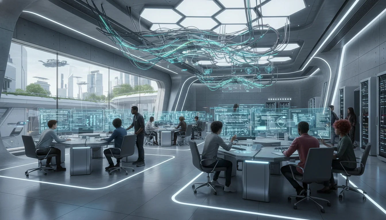
The architectural design and technological implementation of an Information Technology training laboratory represent a highly complex convergence of pedagogical theory, spatial planning, and enterprise-grade infrastructure engineering. As educational paradigms aggressively shift toward active, project-based learning and technological requirements escalate to support artificial intelligence, high-density virtualization, and real-time collaboration, the traditional paradigm of static computing rows is fundamentally obsolete. The modern IT laboratory is no longer merely a classroom equipped with computers; it functions as a high-performance computing node that must meticulously balance the severe thermal and electrical demands of advanced hardware with the ergonomic, visual, and cognitive needs of students and instructors.
Developing an ideal environment for a standard 30-workstation IT training laboratory requires rigorous adherence to multidisciplinary standards to ensure long-term viability and operational safety. This comprehensive framework demands compliance with the Americans with Disabilities Act for spatial routing, Illuminating Engineering Society standards for photometrics, and American Society of Heating, Refrigerating and Air-Conditioning Engineers guidelines for thermodynamics and environmental controls. Furthermore, the selection of computing hardware, hierarchical network switching, uninterrupted power supply topologies, and audio-visual matrixing systems must be engineered to anticipate the intense computational demands of 2026 and beyond. This report provides an exhaustive, evidence-based architectural and technological blueprint for constructing a state-of-the-art IT training laboratory, synthesizing best practices across infrastructure, hardware, and classroom management ecosystems to deliver an optimal pedagogical environment.
Architectural Layout and Pedagogical Spatial Dynamics
The foundational phase in engineering an IT training laboratory is establishing a seating arrangement that optimizes both technological integration and classroom dynamics. The spatial configuration dictates critical sightlines, cable routing efficiency, and the degree of interaction between the instructor and the student cohort. In the context of spatial dynamics, an adaptive approach to desk layout has a profound effect on the classroom, subtly influencing student focus and curbing off-task behavior. A fundamental principle in spatial pedagogy suggests that a static room sends the message that learning is linear and predictable, whereas the modern IT curriculum is dynamic and evolving.
Educational facilities generally deploy one of three architectural topologies: traditional rows, collaborative clusters, or the U-shape (horseshoe) configuration. Each geometry presents distinct advantages and pedagogical trade-offs that must be evaluated against the curriculum’s objectives.
Traditional rows represent the most commonly utilized arrangement in general education, effectively directing all student attention toward the front of the room and the primary instructional display. While this layout supports linear, lecture-based learning and is highly effective for administering formal examinations, it is inherently static. In an IT environment, this layout severely restricts the instructor’s ability to navigate behind students to monitor local screens during complex software development exercises. Furthermore, traditional rows often necessitate lateral cable runs that can create trip hazards and aesthetic degradation if underfloor power distribution is not implemented.
Collaborative clusters, or pods, involve grouping desks to face one another, a geometry that maximizes opportunities for project-based learning, peer programming, and team-based problem solving. However, the primary critical failure of the cluster topology in an IT training environment is the severe degradation of primary sightlines. A significant percentage of students will inherently face away from the instructor and the primary broadcast display. This necessitates constant physical rotation by the students, leading to acute ergonomic strain over prolonged periods and an increased propensity for “side-talking” and off-task behavior. To combat this, instructors must establish strict ground rules regarding communication hierarchies and accountability, which diverts time away from technical instruction.
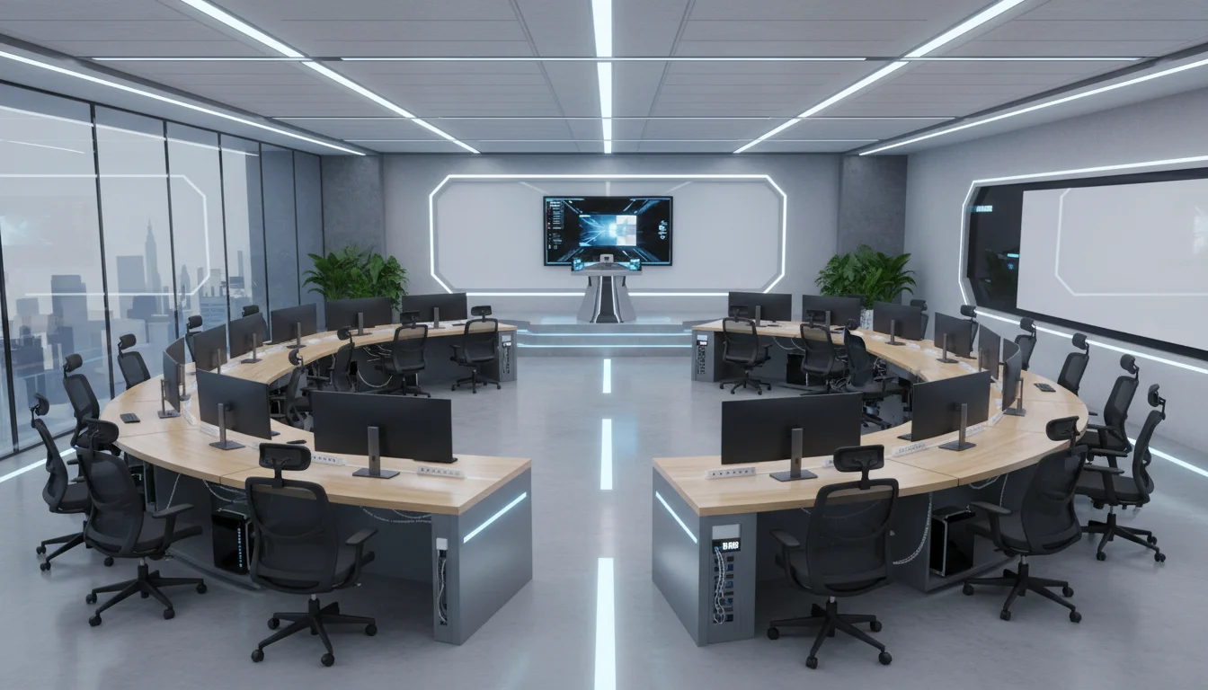
The U-shape, or horseshoe layout, consistently emerges as the optimal architectural topology for high-density IT training laboratories. In this configuration, desks are arranged continuously along the perimeter of the room, leaving a centralized open space. This geometry yields compounding benefits. First, it ensures that all students have clear, unobstructed sightlines to the instructor, the writing boards, and the projection slides. Second, it eliminates the challenge of teaching to students’ backs; the instructor can easily monitor all screens simultaneously from the central “action zone” and move freely to assist individuals. Finally, the continuous perimeter desk arrangement allows electrical and data cables to run seamlessly beneath the tables along the walls, vastly simplifying cable management and power distribution. For a standard 30-student capacity, a double U-shape (comprising an inner and outer horseshoe) is frequently deployed; however, architectural care must be taken to ensure the inner ring does not densely occupy the central area and obstruct the presentation space.
ADA Compliance and Accessibility Dimensions
The architectural layout must rigorously adhere to accessibility standards to ensure equitable access for all users. The U.S. Access Board provides specific, legally mandated dimensional requirements for aisles, turning radii, and desk clearances within educational computing facilities. The integration of these dimensions must occur during the initial computer-aided design phase, as retrofitting accessibility into a dense IT lab is highly disruptive and costly.
Aisle widths must be carefully calculated and strictly maintained, free from protruding objects or temporary obstructions. Side aisles adjacent to workstations must maintain a minimum clear width of 36 inches, while main thoroughfares and primary circulation routes must be at least 44 inches wide. To facilitate the navigation and turning of wheelchair users, the facility must incorporate specific maneuvering clearances. This requires a minimum space consisting of a 60-inch diameter circle, or a 60-by-60-inch T-shaped space intersecting the aisles, allowing for a 180-degree pivoting turn without colliding with desks or specialized equipment. Clear paths to individual workstations can narrow to 32 inches at a specific choke point, such as a doorway or emergency exit, but must otherwise strictly maintain the 36-inch continuous standard.
Table 1 details the required physical dimensions for accessible workstations within the laboratory layout.
| Dimension Parameter | ADA Minimum / Prescribed Standard |
|---|---|
| Work Surface Height | Adjustable between 28 and 34 inches from the finished floor. |
| Horizontal Knee Clearance | Minimum of 30 inches wide, unobstructed by table legs or CPUs. |
| Vertical Knee Clearance | Minimum of 27 inches high from the floor to the lowest under-desk protrusion. |
| Depth of Knee Clearance | Between 17 and 25 inches, extending continuously beneath the surface. |
| Clear Floor Space Footprint | Minimum of 30 inches by 48 inches directly connected to the access aisle. |
| Access to Controls / Ports | Between 15 and 48 inches from the floor (24 to 40 inches highly preferred). |
| Electric Wheelchair Clearance | Vertical clearance of 28 inches from the floor to accommodate specialized chairs. |
For environments where students must transition rapidly between manual writing and computing tasks, corner desk configurations are ergonomically contraindicated. Instead, L-shaped desk returns are mandated. This configuration places the keyboard tray and primary monitor on the straight surface, while positioning the writing return adjacent to the user’s dominant hand, thereby eliminating extreme torso twisting.
Anthropometric Engineering and Specialized Laboratory Furniture
The physiological impact of prolonged computing necessitates that posture optimization be engineered directly into the laboratory’s fundamental design parameters. Ergonomics in a modern IT lab extends far beyond merely providing adjustable seating; it dictates the volumetric space surrounding the user, defining reach envelopes and mitigating musculoskeletal degradation.
Posture Optimization Zones and Seating Mechanics
To engineer safety and comfort into the workspace, the primary work zone must be strictly defined as the 16 inches extending deeply from the bench or desk edge. This zone accommodates 95% of routine manual tasks, including keyboard and mouse operation, without requiring the user to lean forward or overextend their shoulders. A secondary work zone can extend up to a maximum of 24 inches for occasionally accessed peripherals, reference materials, or secondary input devices.
Seating mechanisms represent a critical vector for injury prevention and must adhere to strict biomechanical standards.
Chairs utilized in the laboratory must feature a minimum 5-star base to prevent tipping, equipped with casters appropriate for the flooring substrate—specifically, nylon casters for carpeted environments and rubber casters for linoleum or hard tile. The seat pan depth must be adjustable with minimal contouring to prevent pressure on the popliteal fold behind the knee. The backrest must provide pronounced lumbar support and offer a minimum tilt range of 90 to 105 degrees to support spinal alignment. To accommodate a diverse student body, the desk and chair combination must allow users’ feet to be fully supported by the floor; if the desk height dictates a higher chair cylinder (such as with lab stools), tall footrests or attached structural footrings are mandatory.
High-End Technology Integration Furniture
Standard commercial desks are profoundly inadequate for high-density IT training. The proliferation of dual-monitor setups and large-form-factor workstation CPUs creates severe physical and visual barriers between the instructor and the student, degrading the pedagogical experience and isolating the learner. To resolve this, specialized computer lab furniture engineered by manufacturers such as SMARTdesks, Computer Comforts, and RightAngle must be deployed to harmonize the technology with the space.
These high-end solutions utilize two primary design methodologies to eliminate visual obstruction while securely housing the necessary hardware:
-
Recessed Monitor Platforms
Desks engineered by firms like Computer Comforts feature sub-surface platforms that physically lower the LCD monitors beneath the horizontal sightline of the desk. The user views the screen through a tinted, tempered glass viewport or an open recession. This maintains an unobstructed line-of-sight across the entire room, allowing instructors to maintain eye contact with all students, while simultaneously reducing the student’s cervical spine extension.
-
Mechanized Lift Systems
Convertible solutions, such as the RightAngle Delta View or the SMARTdesks flipIT systems, utilize advanced, gas-assisted vertical lifts that require no electrical power to operate. With a slight manual push, the monitor silently rises from within the desk chassis when technology is required for the lesson. During lectures, examinations, or non-digital collaborative sessions, the monitor is completely stowed beneath the surface, maximizing flat desk space and transforming the IT lab into a highly flexible, multi-use active learning environment.
Furthermore, these specialized desks are engineered with integrated secure CPU storage compartments, modesty panels, and internal wire management raceways. These raceways allow high-voltage power and low-voltage data connectivity to be daisy-chained sequentially between units, deeply integrating with the room’s overarching cable management strategy while completely hiding chaotic cable bundles from the user’s view, thus protecting the cables from accidental kicks or interference. If keyboard trays are utilized, they must adhere to a thin profile (0.25 to 0.375 inches thick) and be wide enough to accommodate a mouse on the exact same contiguous plane; separate, articulated mouse platforms force the shoulder into external rotation and are ergonomically unsound.
Workstation Hardware Specifications (2026 Standards)
Anticipating the hardware demands of 2026 requires acknowledging the paradigm shift brought about by localized artificial intelligence, intensive data processing, and large language model training. Relying solely on cloud compute introduces latency and potential data privacy issues; therefore, workstations in the modern IT lab must act as high-performance edge endpoints capable of rendering complex visualizations, compiling heavy codebases, and executing localized AI models without debilitating bottlenecks.
Core Computational Architecture
The central processing unit (CPU) is the foundational engine of the workstation. An underpowered CPU creates immediate system bottlenecks, rendering high-speed networks and fast storage irrelevant. Standard IT training labs now demand processors equipped with dedicated Neural Processing Units (NPUs) to handle localized AI workloads efficiently without taxing the primary CPU cores. Standard deployments should target the Intel Core Ultra or the AMD Ryzen 5000+ series. For reliable workflows, the CPU should achieve a PassMark ‘CPU Mark’ score of 14,000 to 25,000. For highly specialized labs focused strictly on AI development, 3D rendering, or data science, enterprise-grade processors such as the Intel Core i9-14900K or the AMD Ryzen 9 7950X (featuring 16 or more cores) are absolutely necessary. Future-proofing considerations for late-2026 deployments should account for the release of Intel Nova Lake and AMD Zen 6 architectures, which promise massive leaps in integrated AI acceleration.
Memory bandwidth is equally critical. The 2026 standard dictates a complete transition away from DDR4 memory, establishing DDR5 RAM as the absolute baseline. DDR5 provides a 50% performance increase in data transfer rates while operating at higher energy efficiency than its predecessor. Standard workstations require 16GB to 32GB of DDR5, whereas dedicated AI workstations mandate a minimum of 64GB, scaling up to 128GB to handle scientific computing and the caching of extremely large data models.
Storage must be exclusively solid-state for the operating system and active projects. Massive datasets require the immense throughput of PCIe 4.0 or 5.0 NVMe SSDs, with a minimum capacity of 1TB for standard stations and 2TB for advanced setups. PCIe 5.0 drives offer data loading speeds that are 50% faster than previous generations, drastically reducing classroom downtime when booting complex localized virtual machines or loading massive IDE environments. High-end workstations should utilize hardware-encrypted SSDs (Self-Encrypting Drives) for added security. Additional 4-8TB traditional Hard Disk Drives (HDDs) can be included strictly for cold dataset storage.
The most significant variable in workstation specification, and the primary driver of cost, is the Graphics Processing Unit (GPU). For standard IT training (such as networking protocols, basic web programming, or system administration), modern integrated graphics or entry-level discrete cards are sufficient. However, if the curriculum includes AI model training, machine learning, or complex rendering, a powerful discrete GPU becomes the primary computational engine.
Table 2 outlines the recommended workstation specifications tiered by lab focus.
| Component | Standard IT Training Workstation | Specialized AI & Data Science Workstation |
|---|---|---|
| Processor (CPU) | Intel Core Ultra / AMD Ryzen 5000+ (NPU enabled) | Intel Core i9-14900K / AMD Ryzen 9 7950X (16+ cores) |
| System Memory (RAM) | 16GB to 32GB DDR5 | 64GB to 128GB DDR5 |
| Primary Storage | 1TB Gen4 NVMe SSD | 2TB PCIe 5.0 NVMe SSD (Hardware Encrypted) |
| Graphics (GPU) | Intel/AMD Integrated or Basic Discrete | NVIDIA RTX 5080/5090 or Enterprise RTX 6000 Ada |
| Thermal Cooling | Standard OEM Air Cooling | AIO Liquid Cooling or High-Capacity Tower |
| Power Supply (PSU) | 500W Standard Efficiency | 850W to 1000W+ (80+ Gold or Platinum rated) |
| Operating System | Windows 11 Pro (64-bit) or macOS 13+ | Windows 11 Pro with BitLocker and Copilot |
The extreme power draw of the specialized AI workstations requires robust cooling solutions, as AI workloads generate significant sustained heat. While large tower air coolers ($50-$150) are sufficient for standard tasks, All-in-One (AIO) liquid coolers ($100-$300) provide quieter operation and superior thermal dissipation for sustained computational workloads. Custom liquid cooling loops ($500+) are generally reserved for extreme overclocking and are unnecessary for standard institutional deployments.
Visual Interface and Display Topologies
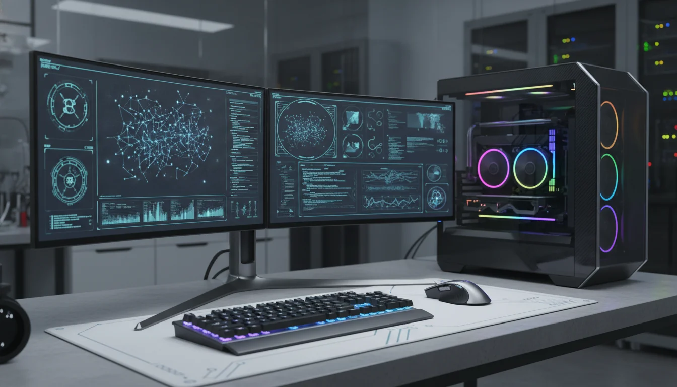
Selecting the optimal visual interface for the workstations is a matter of maximizing workflow efficiency and minimizing cognitive load. The debate within IT infrastructure planning predominantly centers on whether to deploy dual 27-inch monitors or a single 45-inch to 49-inch ultrawide display.
Ultrawide monitors, typically utilizing a 21:9 or 32:9 aspect ratio, provide a massive, seamless canvas that is highly immersive, offering resolutions such as 3440x1440p or 5120x1440p. While excellent for video timelines or massive spreadsheets, in an educational IT lab setting, the dual monitor setup remains vastly superior for productivity. A dual 27-inch configuration (typically utilizing two 16:9 displays at 1440p or 4K resolution) allows for the strict physical partitioning of tasks, which aligns with how developers actually work. A student can dedicate the secondary screen entirely to an instructor’s broadcast feed, reference documentation, or a continuous terminal output, while utilizing the primary screen exclusively for the active Integrated Development Environment (IDE).
To minimize cable clutter, the primary monitor should support daisy-chaining, allowing the secondary display to connect directly to the first, routing a single cable back to the PC. Modern displays should also feature USB-C or Thunderbolt connectivity with Power Delivery (PD) and built-in KVM (Keyboard, Video, Mouse) functionality, allowing students to seamlessly dock personal laptops and control them using the lab’s peripherals.
Ergonomic positioning of these displays is highly regulated. For seated users at fixed desks, the top of the monitor screen must be aligned at 43 to 44 inches from the floor. For standing configurations, this increases to 57 to 58 inches. Dual setups require heavy-duty articulating monitor arms to align the displays seamlessly side-by-side.
The center point where the two monitor bezels intersect must align directly with the user’s midline and the center of the keyboard to prevent asymmetric neck strain. Furthermore, to mitigate visual fatigue, displays must be positioned perpendicular to windows and away from direct overhead lighting to avoid debilitating screen glare.
High-Fidelity Audio-Visual Matrixing and Screen Broadcasting
A critical pedagogical requirement in any computer laboratory is the ability to instantly broadcast the instructor’s screen to the students’ secondary monitors, or conversely, pull a student’s screen to the main projection surface for class analysis and code reviews. This complex routing can be achieved through dedicated hardware matrixes, network-based AV-over-IP, or purely software-driven Classroom Management Systems (CMS).
Hardware Video Matrixing: HDBaseT vs. AV-over-IP
Traditional hardware distribution relies on highly structured cabling to achieve flawless, zero-latency video routing. HDBaseT is a mature, robust standard that utilizes Time-Division Multiplexing (TDM) and Pulse Amplitude Modulation (PAM16) to transmit uncompressed ultra-high-definition video, audio, up to 100W of power, 100Mb/s Ethernet, and control signals (IR, RS-232, CEC) simultaneously over a single standard Cat5e/6 cable. Known as the “5Play” feature set, HDBaseT operates flawlessly for distances up to 100 meters (330 feet) without the need for signal repeaters. However, HDBaseT distribution is fundamentally limited by the physical chassis size of the matrix switcher (e.g., a rigid 16x16 or 8x8 matrix), making future expansion beyond the port count highly problematic and expensive.
For a dynamic, 30-workstation lab that may scale, AV-over-IP (Audio-Visual over Internet Protocol) represents a vastly superior and scalable architecture. AV-over-IP replaces the centralized, physical matrix switcher with standard Ethernet networking equipment. Video from a source is fed into a dedicated encoder, packetized, routed through standard Layer 2/Layer 3 Gigabit switches, and unpacked by decoders attached to the displays. This creates a flexible “virtual matrix” with infinite scalability; adding a new workstation simply requires plugging a new encoder/decoder node into the existing local area network. While near-lossless codecs like JPEG-XS are utilized to maintain visual fidelity, minor compression is present, and latency is slightly higher than HDBaseT, though this delay is generally imperceptible in a standard classroom setting. Systems from Visionary Solutions or SVSi are frequently deployed in these environments.
If broadcast-level zero-latency routing is an absolute mandate, high-end baseband routers, such as the Blackmagic Videohub 12G-SDI, must be deployed. These advanced units handle any combination of SD, HD, and Ultra HD video concurrently, allowing instructors to manipulate cross-point routing electronically without altering physical cables. Control ecosystems from manufacturers like Extron and Crestron provide intuitive, custom-programmed touch-panel interfaces for the instructor’s lectern. These panels orchestrate the complex routing configurations, managing both the video matrix and the room’s overarching audio and lighting systems simultaneously.
Software-Defined Classroom Management Systems (CMS)
While hardware matrixing guarantees absolute signal integrity, modern pedagogy increasingly favors the vast, interactive feature sets provided by Classroom Management Software (CMS). Software platforms such as classroom.cloud, Faronics Insight, Mobile Guardian, and Vivi allow for wireless screen sharing directly over the existing data network without the need for dedicated HDMI encoders, SDI cables, or expensive physical matrix switchers.
Beyond mere video broadcasting, a CMS transforms the instructor into a holistic network orchestrator, drastically reducing off-task behavior. While some IT administrators argue that such software encourages instructors to remain stationary at their desks rather than moving about the room, when used correctly, it acts as a powerful force multiplier for classroom management.
Table 3 outlines the critical features of a modern IT training CMS.
- CMS Feature Category
- 2026 Core Capabilities and Implementations
- Device Monitoring & Remote Control
- Real-time screen viewing of all 30 clients, remote PowerShell script execution, and seamless device lock/unlock mechanisms to force attention.
- Content & Application Filtering
- The ability to whitelist or blacklist specific websites and applications dynamically, ensuring students remain engaged strictly within the designated development environment.
- Safeguarding and AI Integration
- Advanced keyword monitoring across 20,000+ terms, AI-driven analysis to detect harmful images or content, and phrase clouds mapping trending local topics.
- Assessment and Interactivity
- Instant deployment of quizzes, polls, and exit tickets directly to the student UI, paired with real-time LMS and gradebook synchronization.
- Power Management
- Centralized scheduling to remotely power on, reboot, or log off the entire 30-machine fleet simultaneously, drastically reducing administrative overhead.
CMS implementations drastically reduce the required capital expenditure on specialized AV hardware. Furthermore, advanced educators can integrate external assessment tools like Kahoot (gamification), Padlet (real-time collaboration), and Genially (interactive presentations) to further engage the digital-native student body. However, because CMS platforms stream high-resolution video data and continuous telemetry across the LAN, they impose significant demands on the underlying network infrastructure.
Core Network Infrastructure and Telemetry Architecture
The efficacy of localized AI processing, AV-over-IP video distribution, and CMS orchestration hinges entirely on the architectural integrity and bandwidth capacity of the local area network. A 30-student IT training lab, particularly one situated within a broader educational campus, requires a rigorous, hierarchical three-tier network design consisting of Core, Distribution, and Access layers to ensure flawless data delivery.
The Three-Tier Network Hierarchy
- Access Layer (Edge): This is the physical edge of the network where the 30 workstations, IP phones, AV decoders, and wireless access points terminate. Access switches operate primarily at Layer 2 of the OSI model, utilizing MAC addressing to switch frames. Standard modern access switches provide 1Gbps to 10Gbps copper ports depending on the specific endpoint requirements. Crucially, the access layer handles Virtual LAN (VLAN) assignments. The IT lab must be logically segmented into its own VLAN to isolate its heavy, broadcast-intensive traffic from the administrative, faculty, and general student networks, thereby minimizing broadcast domains and enhancing overarching security.
- Distribution Layer (Aggregation): Distribution switches serve as the critical intermediary, aggregating the massive uplinks from dozens of access switches across the facility. Operating primarily at Layer 3, these managed switches route packets between different VLANs (Inter-VLAN routing) and enforce critical security and Quality of Service (QoS) policies. Strict QoS implementation is absolutely vital in this environment; it prioritizes latency-sensitive AV-over-IP streams and CMS control commands over bulk file downloads, ensuring the video broadcast does not stutter when a student initiates a large data pull.
- Core Layer: The core is the high-speed backbone of the network, engineered solely for raw throughput and immense traffic loads with near-zero latency. To reduce processing complexity and maximize speed, the core layer typically carries only routed Layer 3 traffic. Modern architectures utilize advanced technologies like Virtual Switching Extension (VSX) and multiple Equal-Cost Multipath (ECMP) routing to unify the data plane between core switches while maintaining separate control planes. This ensures extreme redundancy, allowing for instantaneous failover if a core node experiences a catastrophic hardware fault.
Bandwidth and Capacity Planning
Students in advanced IT programs interact with multiple networked devices concurrently. Historical data models indicate that K-12 students maintain 2 to 3 connected devices, while higher education students often bring 4 to 5 devices to campus (laptops, phones, tablets, smartwatches). To prevent debilitating bottlenecks during concurrent activities (e.g., all 30 students pulling a heavy Docker container simultaneously or compiling code against a central repository), bandwidth must be meticulously calculated.
The FCC and SETDA guidelines recommend a baseline internet access bandwidth of 3 Gbps for a medium-sized institution (approximately 3,000 students). However, the dedicated IT lab requires localized gigabit throughput directly to the distribution layer, supported by Wi-Fi 6 or 6E access points to handle the immense density of wireless connections. Furthermore, the network must integrate robust security, including CIPA-compliant content filtering and captive portals to manage inactive sessions. Rigorous simulations using tools like Cisco Packet Tracer and GNS3 are strongly recommended prior to physical deployment to accurately model traffic flows, test QoS policies, and validate network resilience under peak stress scenarios.
Electrical Topologies, UPS Redundancy, and Cable Management
High-performance workstations, specialized AIO cooling, and dense network switches require a robust, flexible, and fail-safe power topology.
Managing the immense electrical requirements of a 30-workstation lab involves evaluating overhead versus underfloor distribution, localized cable management strategies, and precise Uninterruptible Power Supply (UPS) scaling.
Power Topologies: Overhead vs. Underfloor Distribution
Power and data can be distributed to the laboratory floor via two primary architectural pathways:
Underfloor Distribution
This approach utilizes a raised access floor, where a rigid grid of horizontal and vertical bars is laid across the concrete slab, supporting removable floor tiles. Electrical conduits, data cables, and high-capacity busbars are routed completely out of sight beneath the floor and brought directly to the workstations via recessed floor boxes. Floor boxes contain separate, physically shielded compartments for high-voltage power and low-voltage data (Ethernet, HDMI) to prevent debilitating electromagnetic interference (EMI). This topology preserves the room’s clean aesthetic, entirely eliminates trip hazards, and offers supreme flexibility for future reconfigurations; moving a desk simply involves swapping a blank floor tile for a ported one.
Overhead Distribution
Power and data are suspended from the ceiling in metal wire-mesh trays and delivered downward to the desks via structural power poles. These power poles feature divided internal channels separating data and electrical lines. While overhead distribution requires a significantly lower initial capital expenditure and consumes less volumetric space than constructing a raised floor, the vertical poles introduce severe visual clutter and can interfere with projection sightlines, making it a suboptimal choice for a highly visual educational environment.
Cable Management Best Practices
Within the individual desk units and centralized server/network racks, rigorous cable management is essential for both thermal regulation and ongoing maintenance. Disorganized, tangled cables restrict airflow within server racks, trapping heat and degrading component efficiency, which can lead to thermal throttling or premature hardware failure.
Best practices dictate grouping cables strictly by function (e.g., bundling power lines entirely separately from data connections) using hook-and-loop (Velcro) straps. Plastic zip ties must be explicitly avoided; they cannot be easily adjusted during reconfigurations and are frequently over-tightened, which pinches delicate Cat6 or fiber optic cables, altering their geometry and causing severe signal degradation. Furthermore, establishing a strict, comprehensive labeling protocol at both ends of every single cable drastically reduces troubleshooting time and minimizes human error during critical maintenance windows or upgrades.
UPS Sizing and Power Redundancy
Power anomalies—ranging from micro-sags to total blackouts—are catastrophic to localized data, volatile memory, and sensitive IT equipment. An online double-conversion UPS system is mandatory for the lab’s core infrastructure, as it completely isolates the hardware from the raw utility power. It continuously converts incoming AC to DC, and back to a perfectly clean, regenerated AC sine wave, free from voltage fluctuations.
Calculating the required UPS capacity involves aggregating the total wattage (or VA) of all connected equipment (workstations, monitors, matrix switchers, and local networking gear). Once this baseline IT load is established, a 35% growth buffer must be applied—25% to accommodate projected future hardware expansions and 10% to account for battery aging and efficiency losses over time. For example, if the calculated load of the lab is 13.5 kVA, multiplying by the 1.35 headroom factor necessitates a UPS system capable of handling approximately 18.2 kVA.
Redundancy is equally critical to prevent a single point of failure. An N+1 redundancy model is the gold standard for training laboratories; this involves deploying a modular UPS frame where ‘N’ represents the necessary capacity modules, and ‘+1’ represents an actively connected, hot-swappable spare module capable of instantaneously assuming the load if a primary module fails. Battery cabinets should be sized to provide 15 to 30 minutes of runtime, allowing sufficient time for students to save configurations gracefully, or for building diesel generators to start and stabilize.
Within the equipment racks themselves, power is distributed via 0U vertical Power Distribution Units (PDUs). By mounting vertically on the rear rails of the server cabinet, 0U PDUs conserve highly valuable horizontal rack space (U-space) while providing up to 40 metered receptacles. Advanced metered PDUs enable IT administrators to monitor amperage draw at the granular, per-outlet level and remotely reboot hung servers without entering the lab.
Thermodynamics and Precision Environmental Controls
The extreme density of computing hardware in a 30-workstation IT lab transforms the space into a severe thermal environment. Building-level HVAC systems are generally engineered for standard human comfort and are profoundly ill-equipped to handle the concentrated, relentless sensible heat generated by server racks, GPU-accelerated workstations, and large displays.
Thermal Load Calculations and Psychrometrics
Electronic devices convert almost 100% of their consumed electrical power directly into heat. Therefore, precision cooling is an absolute requirement. The target ambient temperature for a computer laboratory must be maintained between 18°C and 27°C (ideally optimized between 18-25°C), with a strictly controlled relative humidity of 45% to 50%. Deviations outside this narrow humidity band lead to condensation on cold metal substrates if the air is too damp, or an increased risk of electrostatic discharge (ESD) capable of destroying sensitive integrated circuits if the air becomes too dry.
Calculating the room’s total thermal load requires evaluating multiple distinct factors, measured in British Thermal Units (BTU) per hour. The mathematical baseline involves aggregating the heat from all sources within the envelope:
- Device Heat: Every watt of power consumed by the IT equipment produces exactly 3.412 BTUs. If 30 high-end workstations draw 500W each, the baseline hardware load is.
- Occupancy: Each human occupant contributes approximately 400 to 600 BTUs/hour of mixed sensible and latent heat.
- Architectural Heat Gain: The square footage, ceiling height, and solar gain through windows (ranging from 700 BTUs for Low-E glass to 1200 BTUs for standard single-pane) must be factored into the equation, modulated by the building’s insulation quality multipliers.
Air conditioning systems perform two distinct functions: sensible cooling (lowering the dry-bulb temperature of the air) and latent cooling (removing moisture from the air). The capacity of the system to drop the physical temperature is governed by the equation:
Where represents the sensible capacity in BTU/hr, is the airflow in cubic feet per minute, and is the temperature differential across the cooling coil.
However, to account for total capacity, which includes latent moisture removal, the air enthalpy (, measured in BTU per pound of dry air) is evaluated using a psychrometric chart. The total cooling capacity then becomes:
To distribute this highly conditioned air efficiently without subjecting students to uncomfortable, distracting drafts (air velocity at workstations must absolutely not exceed 50 feet per minute), cold aisle containment strategies and directional high-flow floor tiles are frequently utilized in conjunction with the raised floor. Within any localized server racks, HotLok blanking panels must be installed in empty U-slots to physically prevent the hot exhaust air from bypassing the cooling stream and recirculating back into the equipment’s front intakes.
Photometrics, Lighting Design, and Acoustic Mitigation
The environmental comfort of an IT laboratory extends deeply into the realms of photometrics and acoustics. Visual fatigue and auditory distraction are primary drivers of cognitive fatigue, drastically reducing information retention and endurance during complex programming or networking tasks.
Photometric Standards and Illuminance
Proper lighting design in an IT lab must strike a precise balance: it must be bright enough to illuminate physical texts, keyboards, and hardware, yet controlled enough to prevent harsh glare on LCD screens and projection surfaces.
The Illuminating Engineering Society (IES) establishes the global benchmark standards for spatial lighting, measured in foot-candles (fc) or lux, where 1 foot-candle is approximately equal to 10.76 lux. For a standard educational laboratory or classroom, the IES recommends maintaining a light level between 50 and 75 foot-candles (500 to 750 lux). However, if the IT laboratory is utilized for professional-level tasks requiring high visual acuity—such as tearing down hardware, splicing fiber optic cables, or circuit board analysis—the illuminance standard increases significantly to 75-120 foot-candles (750 to 1200 lux).
LED fixtures are heavily favored over legacy fluorescent tubes due to their high energy efficiency (offering up to 50% savings in consumption), extended operational lifespan, and the ability to integrate seamlessly with occupancy sensors and automated daylight harvesting systems to reduce long-term costs. Crucially, the fixtures must employ indirect diffusion or deep parabolic louvers to minimize the vertical illuminance that causes debilitating screen glare.
Acoustic Mitigation in Server and Network Racks
Localizing servers, core switches, and UPS systems within the same room as the students introduces severe auditory disruptions.
Acoustic Management
The enterprise-grade fans utilized in modern 1U and 2U servers operate at extremely high RPMs to force air through dense, hot chassis, creating loud, high-frequency mechanical noise that permeates the learning environment.
To preserve the acoustic integrity of the pedagogical environment, specialized soundproofing methodologies must be applied directly to the equipment racks.
- Acoustic Cabinets: Procuring an engineered “UCoustic” or low-noise server enclosure is the primary line of defense. These specialized cabinets are heavily sealed and designed to absorb acoustic energy while maintaining vital airflow channels for heat dissipation.
- Mass and Absorption Layering: True soundproofing requires a precise combination of blocking and absorbing materials. Acoustic foam applied to the interior doors absorbs the high-frequency fan noise, while heavy layers of Mass-Loaded Vinyl act as a dense barrier to physically block the transmission of lower-frequency soundwaves out of the cabinet.
- Vibration Isolation: The mechanical energy generated by spinning hard drives and high-speed cooling fans can transfer directly into the floor or walls as resonant, low-frequency hums. Installing heavy-duty anti-vibration pads beneath the cabinet decouples the rack from the architecture, severing the path of acoustic resonance. In instances where standard server fans are too loud, integrating specialized low-noise fans, such as those produced by Noctua, can dramatically reduce the decibel output, though care must be taken to ensure they meet the thermal requirements of the hardware.
Furthermore, custom-cut sound barrier blankets, which must be Class A fire rated, can be suspended behind racks or affixed to adjacent walls to deaden up to 90% of the noise bleeding into adjoining spaces, provided they are configured with cutouts that do not restrict the equipment’s vital exhaust pathways.
Conclusion
The construction of an ideal IT training laboratory is not an exercise in merely assembling discrete hardware components; it is an exercise in complex, highly integrated systems engineering. The architectural topology of the U-shape layout, combined with strict ADA spatial compliances and highly engineered recessed-monitor furniture, sets the physical stage for unhindered, dynamic pedagogical interaction. The integration of 2026-standard NPU-enabled processors, DDR5 memory, and dual-display arrays ensures that the computational power matches the rigors of modern AI, virtualization, and developmental workflows.
However, the efficacy of this outward-facing hardware relies entirely on the invisible infrastructure operating tirelessly behind the walls, above the ceilings, and beneath the floors. A scalable AV-over-IP and Software-Defined CMS ecosystem must be underpinned by a robust, three-tier Layer 3 network architecture capable of near-zero latency switching and massive bandwidth aggregation. In tandem, precision thermodynamics must be calculated down to the exact BTU to counter the massive localized heat loads, supported by highly resilient, N+1 redundant double-conversion power topologies. By meticulously applying the physical, electrical, thermal, acoustic, and network standards outlined in this exhaustive report, institutions can successfully deploy an IT laboratory that serves as a resilient, high-performance crucible for advanced technological education.